AGR Gear-Driven Rotary Stages
Our versatile AGR gear-driven rotary stages bring you significant advantages in load capacity, long-term positioning performance and reliability over other gear-driven rotary positioners. Available in five models with apertures ranging from 50 mm to 200 mm diameters, AGR stages are well equipped to address a wide range of single- and multi-axis applications for general-purpose positioning in industrial and laboratory settings.
Interested in buying online? Learn more here.
Description
Specifications
Dimensions
Ordering Info
Downloads
Description
Description
Specifications
Dimensions
Ordering Info
Downloads
Description
Design Features
- Features large, clear aperture up to 200 mm for mounting optics, cameras, process equipment, cabling & more
- Configurable with direct encoder option for enhanced positioning precision
- Accommodates payloads up to 425kg
- Offers continuous 360° rotation with configurable travel limits available
- Integrates easily in multi-axis configurations
Key Applications
AGR stages are ideal for a variety of precision industrial and laboratory applications, including:
- Laser processing
- Measurement & inspection
- Sample positioning
- Nondestructive testing
- Pointing, scanning & tracking
- Integration into gimbal systems
Construction Features
The presence of a large, clear aperture in the stage allows the AGR series to address applications requiring a through-hole or accommodations to mount an optic, including articulation of beam polarizing lenses, through-holes for cabling and/or air lines, or vision/camera/inspection applications.
The AGR stage base is fabricated from an aluminum alloy that offers significant weight savings in multi-axis arrangements and other weight critical applications, while providing high structural stiffness and long-term stability.
Each stage is designed with two high-precision angular contact bearings with optimal spacing to provide excellent error motions coupled with high load capacities in a small, compact package.
Flexible Options
Options include flexible motor selections as well as a direct encoder mounted to the stage shaft for outstanding repeatability and to virtually eliminate hysteresis and backlash. Vacuum-compatible versions (for use in pressures as low as 10-6 torr) are also available.
Motor and Drives
Standard AGR stage configurations feature Aerotech’s brushless servomotors. However, all AGR stages can be outfitted with stepper or DC brush motors. A full range of matching drives and controls are available for a complete single-source solution.
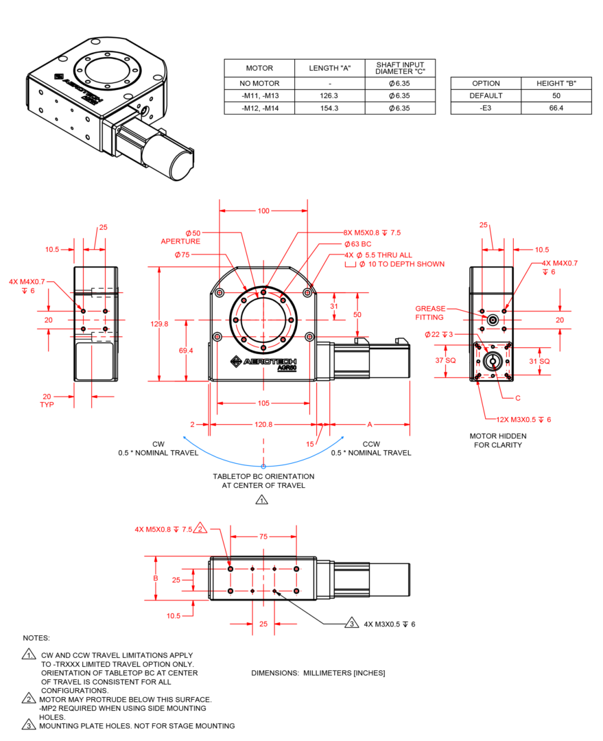
Dimensions
AGR50
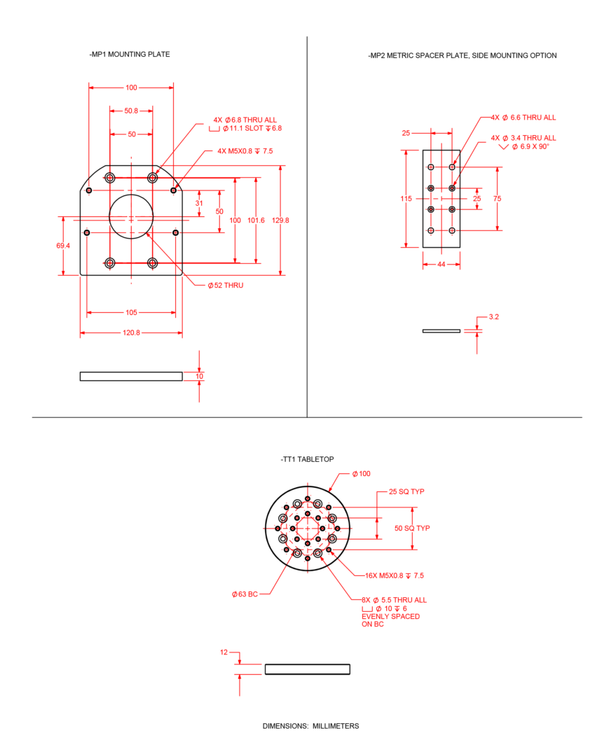
AGR50 Accessories
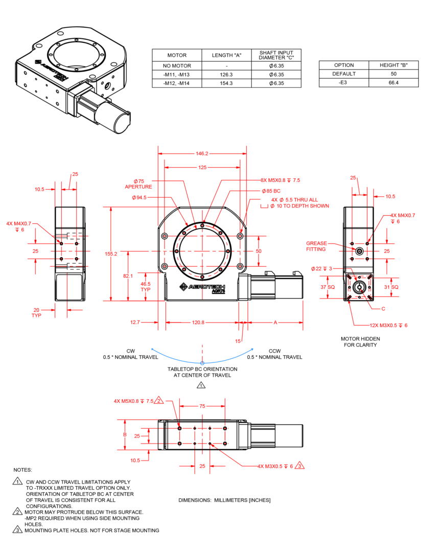
AGR75
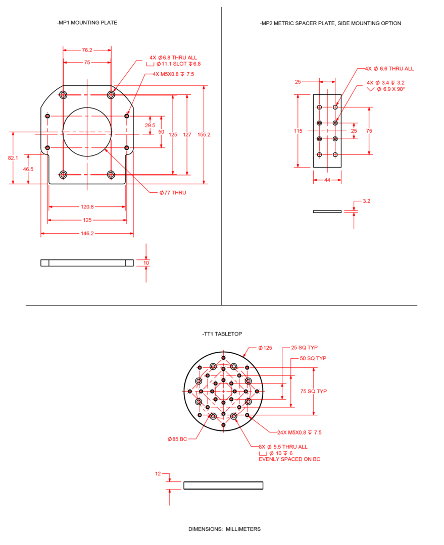
AGR75 Accessories
AGR100
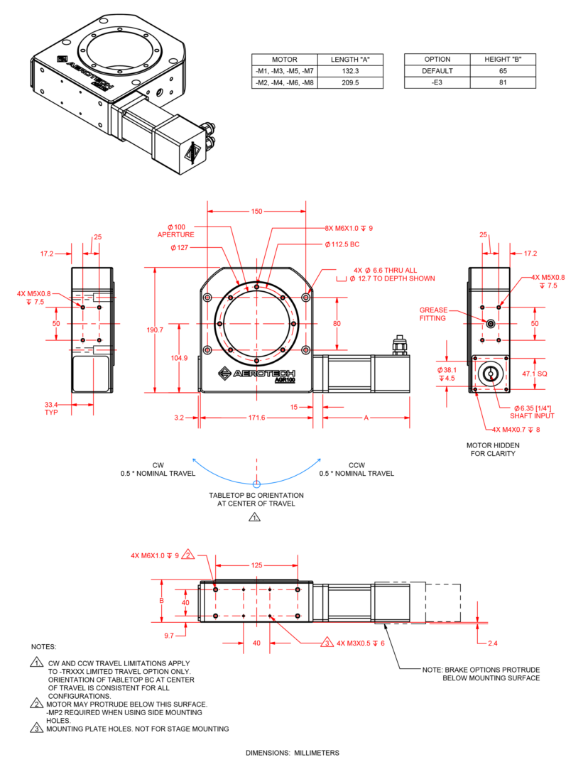
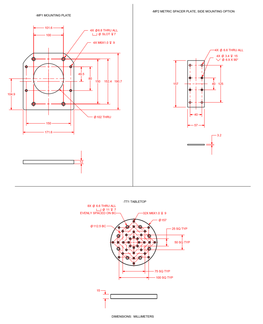
AGR100 Accessories
AGR150
AGR150 Accessories
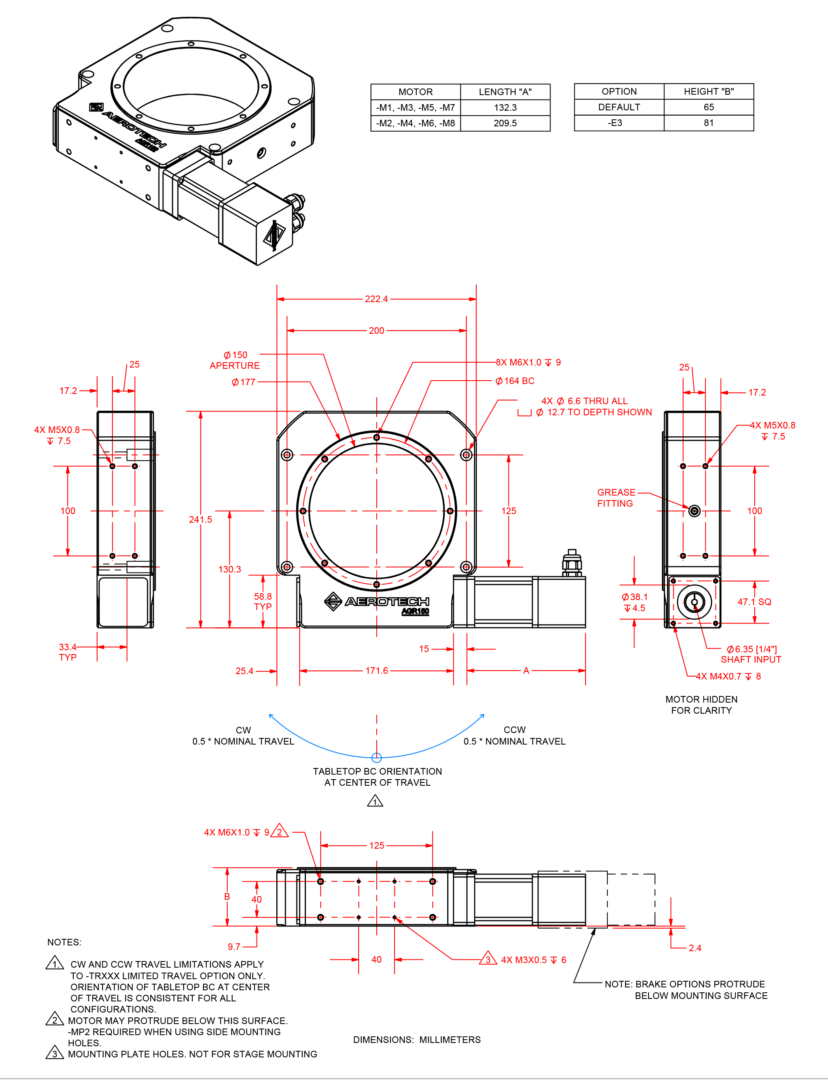
AGR200
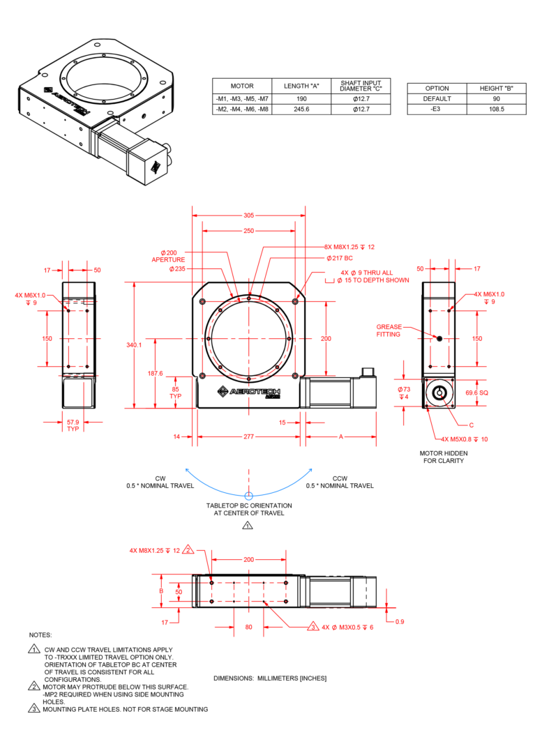
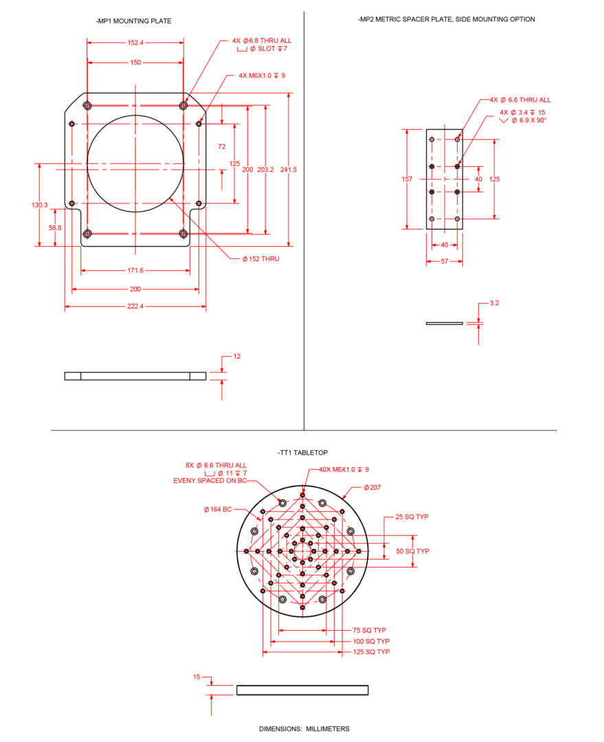
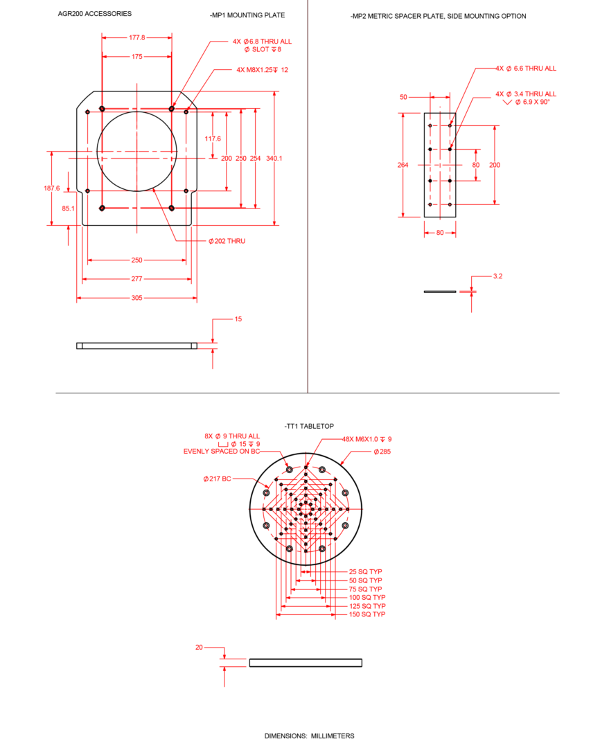
AGR200 Accessories
AGR Motor Orientation
Ordering Information
AGR Series Gear-Driven Rotray Stages
Model (Required)
| Option | Description |
| AGR50 | Gear-driven rotary stage, 50 mm diameter clear aperture |
| AGR75 | Gear-driven rotary stage, 75 mm diameter clear aperture |
| AGR100 | Gear-driven rotary stage, 100 mm diameter clear aperture |
| AGR150 | Gear-driven rotary stage, 150 mm diameter clear aperture |
| AGR200 | Gear-driven rotary stage, 200 mm diameter clear aperture |
Motor (Optional)
| Option | Description |
| -M5 | BM75 brushless servomotor and 2500-line TTL encoder (AGR100, AGR150) BM250 brushless servomotor and 2500-line TTL encoder (AGR200) |
| -M6 | BM75 brushless servomotor and 2500-line TTL encoder with brake (AGR100, AGR150) BM250 brushless servomotor and 2500-line TTL encoder with brake (AGR200) |
| -M7 | BM75 brushless servomotor and 1000-line 1 Vpp encoder (AGR100, AGR150) BM250 brushless servomotor and 1000-line 1 Vpp encoder (AGR200) |
| -M8 | BM75 brushless servomotor and 1000-line 1 Vpp encoder with brake (AGR100, AGR150) BM250 brushless servomotor and 1000-line 1 Vpp encoder with brake (AGR200) |
| -M11 | BM24 brushless servomotor and 2500-line TTL encoder (AGR50, AGR75) |
| -M12 | BM24 brushless servomotor and 2500-line TTL encoder with brake (AGR50, AGR75) |
| -M13 | BM24 brushless servomotor and 1000-line 1 Vpp encoder (AGR50, AGR75) |
| -M14 | BM24 brushless servomotor and 1000-line 1 Vpp encoder with brake (AGR50, AGR75) |
- Other motor options are available upon request. Contact Aerotech for more information.
Motor Location (Required)
| Option | Description |
| -ML1 | Motor located on right side of stage housing, standard (see diagram) |
- Other motor location and orientation options are available upon request. Contact Aerotech for more information.
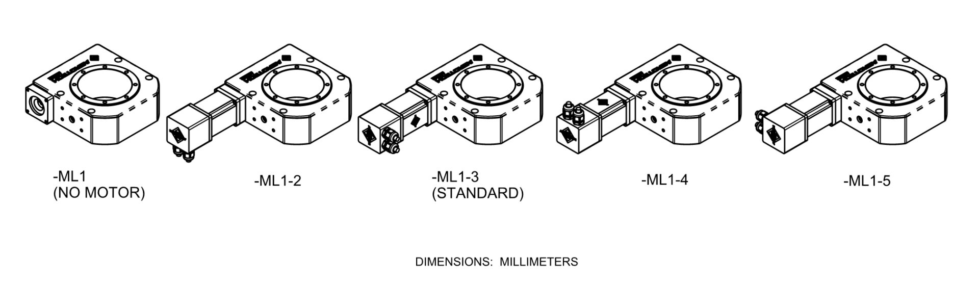
Motor Orientation (Optional)
| Option | Description |
| -2 | Motor orientation 2 |
| -3 | Motor orientation 3, standard |
| -4 | Motor orientation 4 |
| -5 | Motor orientation 5 |
- See diagram for details.
Travel (Required)
| Option | Description |
| Continuous travel (standard) | |
| -TR015 | Limited travel, ±7.5 degrees |
| -TR030 | Limited travel, ±15 degrees |
| -TR045 | Limited travel, ±22.5degrees |
| -TR060 | Limited travel, ±30 degrees |
| -TR075 | Limited travel, ±37.5 degrees |
| -TR090 | Limited travel, ±45 degrees |
| -TR105 | Limited travel, ±52.5 degrees |
| -TR120 | Limited travel, ±60 degrees |
| -TR135 | Limited travel, ±67.5 degrees |
| -TR150 | Limited travel, ±75 degrees |
| -TR165 | Limited travel, ±82.5 degrees |
| -TR180 | Limited travel, ±90 degrees |
| -TR195 | Limited travel, ±97.5 degrees |
| -TR210 | Limited travel, ±105 degrees |
| -TR225 | Limited travel, ±112.5 degrees |
| -TR240 | Limited travel, ±120 degrees |
| -TR255 | Limited travel, ±127.5 degrees |
| -TR270 | Limited travel, ±135 degrees |
- -TRxxx limited travel options contain an extra 2 degrees of overtravel between the nominal travel and the electrical limit on each side (Ex: -TR270 contains ±135 degrees of nominal travel, with ±137 degrees of travel between electrical limits).
Limits (Required)
| Option | Description |
| -Ll1 | Normally-closed end-of-travel limited switch with 9-pin connector |
- Limits option is only available with limited-travel configurations. Other limit options are available upon request. Contact Aerotech for more information.
Direct Rotary Feedback (Optional)
| Option | Description |
| -E3 | Direct, square-wave TTL, output encoder, x50 multiplier |
- Other direct rotary feedback options are available upon request. Contact Aerotech for more information.
Tabletop (Optional)
| Option | Description |
| -TT1 | Metric tabletop |
- Other tabletop options are available upon request. Contact Aerotech for more information.
Mounting Plate (Optional)
| Option | Description |
| -MP1 | Universal English/metric mounting plate |
| -MP2 | Metric Spacer Plate, Side Mounting Option |
Metrology (Required)
| Option | Description |
| -PL0 | No metrology performance plots |
| -PL1 | Metrology, uncalibrated with performance plots |
| -PL2 | Metrology, calibrated (HALAR) with performance plots |
Integration (Required)
Aerotech offers both standard and custom integration services to help you get your system fully operational as quickly as possible. The following standard integration options are available for this system. Please consult Aerotech if you are unsure what level of integration is required, or if you desire custom integration support with your system.
| Option | Description |
| -TAS | Integration - Test as system Testing, integration, and documentation of a group of components as a complete system that will be used together (ex: drive, controller, and stage). This includes parameter file generation, system tuning, and documentation of the system configuration. |
| -TAC | Integration - Test as components Testing and integration of individual items as discrete components that ship together. This is typically used for spare parts, replacement parts, or items that will not be used together. These components may or may not be part of a larger system. |