Aerospace & Defense, Capability Overview, Electronics, Gantries, Gimbals & Optical Mounts, Laser Scan Heads, Laser Systems, Medical Device Manufacturing, Motion Control Platforms, Motors, Piezoelectric Nanopositioners, Precision Manufacturing, Process-Specific Products, Stages & Actuators
Capability Overview
Enhanced Tracking Control (ETC)
Aerotech’s unique Enhanced Tracking Control (ETC) feature improves move-and-settle times in point-to-point positioning and reduces tracking errors during contoured motion. It is a standard feature on the Automation1 control platform and should always be applied when using the Automation1-GL4 high-performance galvo scan head drive. The Enhanced Tracking Control algorithm works in parallel with a conventional Proportional-Integral-Derivative (PID) control architecture and increases the ability of the servomechanism to reject disturbances that would otherwise lead to position errors.
Background
Bearing friction leads to many of the dynamic errors in precision positioning systems. A simple Coulomb friction model is adequate for large-scale motions, but the behavior at micron-levels and below is much more complex. The interaction of multiple rolling elements with varying preloads and lubrication levels leads to a hysteretic relationship between the applied force and resulting displacement. Simply put, the mechanics do not move as far as linear servo theory predicts they should. The result is a long tail in the settling time as the controller tries to pull the stage through to the final position, or to peaks in the position error when a stage changes direction.
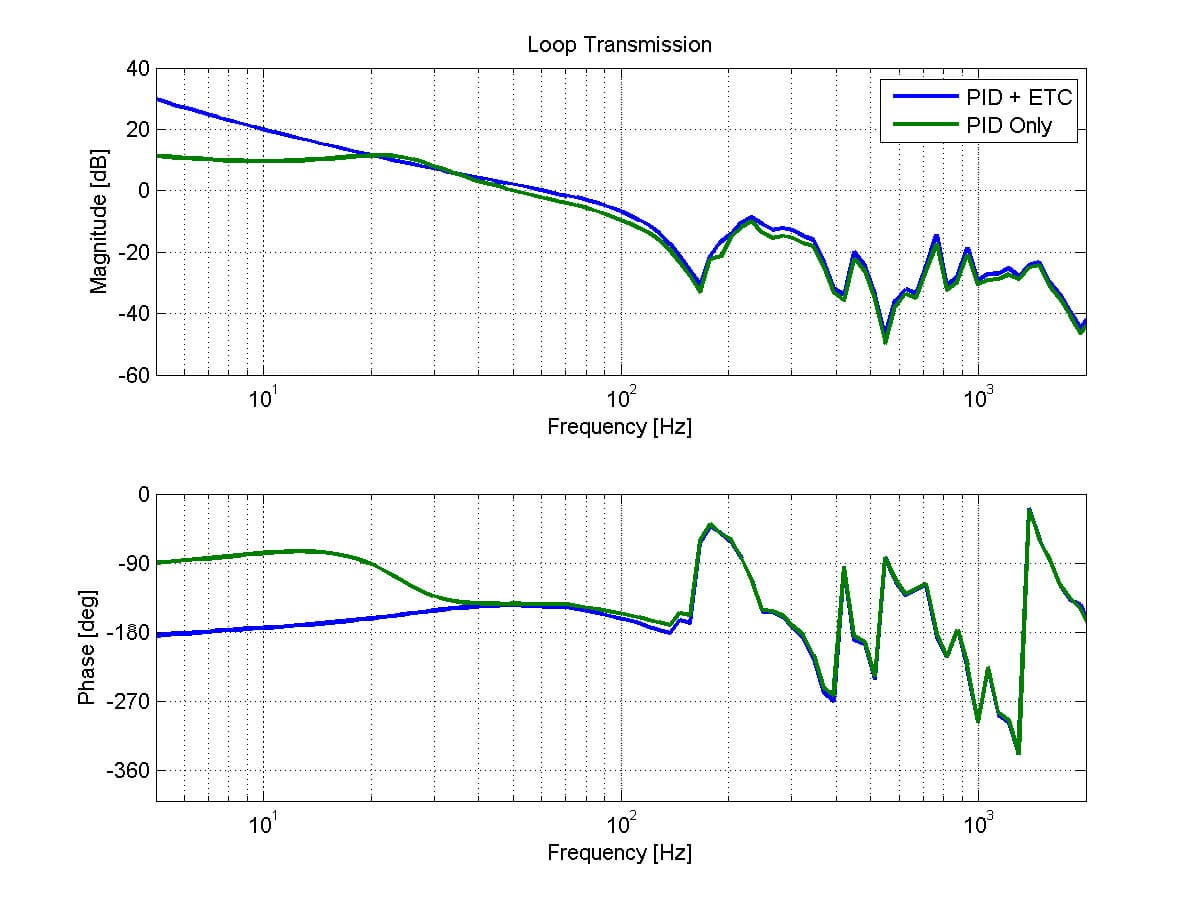
The influence of bearing friction is clearly indicated by a frequency response plot of the servo loop gain (Figure 1). An ideal response transitions smoothly from high gain at low frequencies (indicating good control authority) through the crossover frequency to low gain at high frequencies (necessary to prevent unwanted machine vibrations). Bearing friction creates a diminished response at low frequencies, and lower loop gain means a slower response to disturbances. The Enhanced Tracking Control algorithm boosts low frequency response of servomechanisms leading to dynamic behavior much closer to an ideal frictionless system.
Tuning Technique
The Enhanced Tracking Control algorithm is straightforward to tune, and generally requires no changes to the existing PID gains. The system should first be conventionally tuned for good performance and stability metrics, preferably quantified with an overall loop transmission measurement. The Enhanced Tracking Control feature requires just two additional parameters: a scale factor and a bandwidth. An autotuning algorithm identifies the scale factor (a combination of the inertia, motor force constant and sensor resolution), and the bandwidth is set to be a modest fraction of the controller crossover frequency.
Improvements in Point-to-Point Positioning
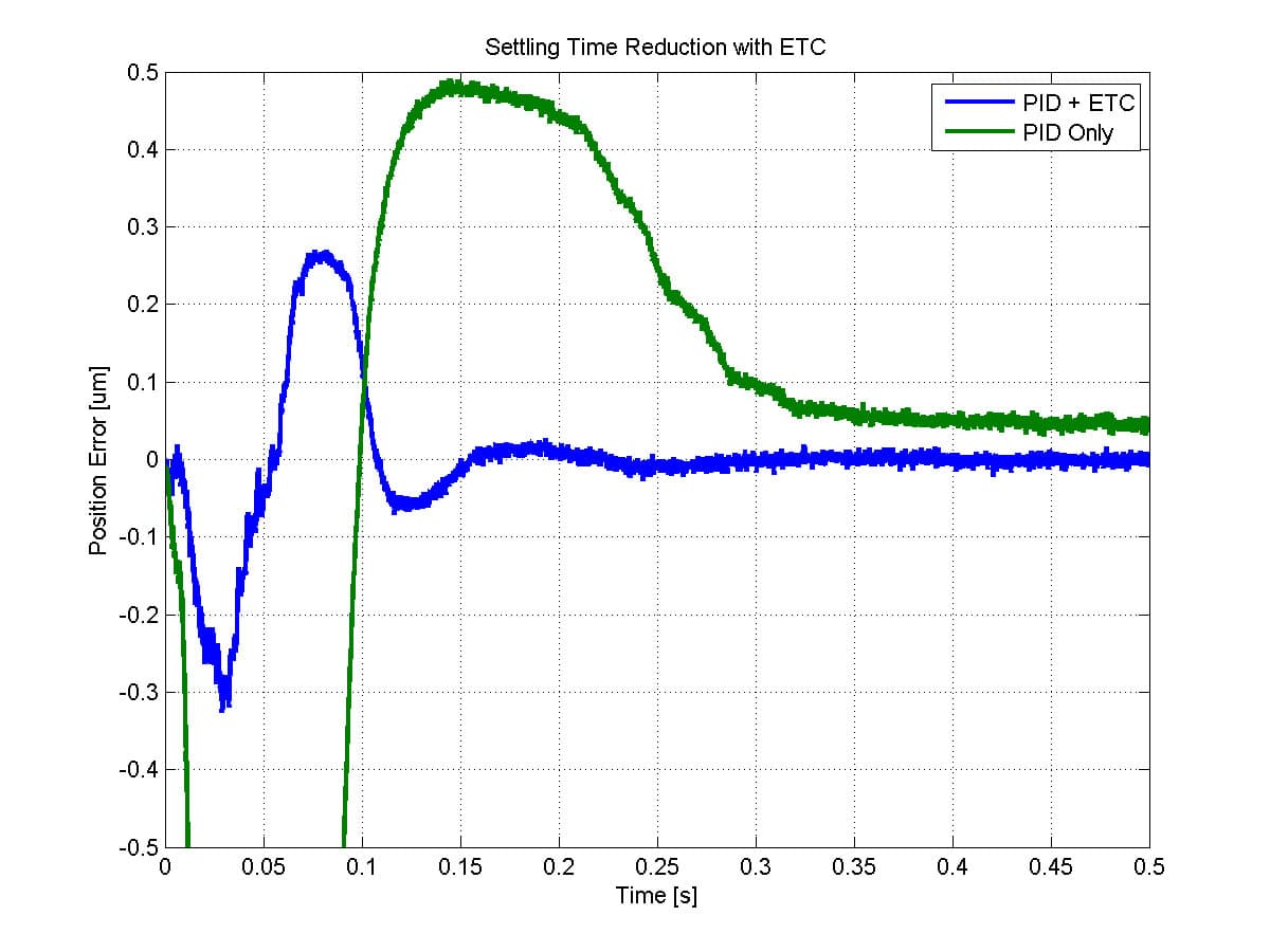
The Enhanced Tracking Control algorithm improves point-to-point positioning performance by eliminating the long tail associated with settling to sub-micron tolerances (Figure 2). Systems with rolling element bearings typically take a long time in the quasi-static condition when the rolling elements are almost, but not quite, in their final position. The higher loop gain of the servo at low frequencies provides the additional effort to push through the bearing friction when using the Enhanced Tracking Control algorithm.
Improvements in Dynamic Tracking
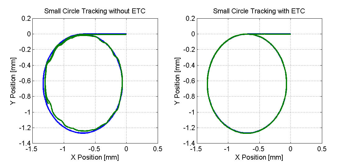
Dynamic tracking performance also improves when the Enhanced Tracking Control algorithm is used to reject disturbance forces. Tracking errors are usually worse at direction reversals, and small circle profiles are one of the most challenging for a servomechanism to track. Figure 3 shows a 4x reduction in peak tracking errors when the ETC is applied to a complex contour as might be seen in a laser cutting application.
Improvements in Galvo Mirror Control
The lightweight mirrors used in high-speed laser galvanometers are especially susceptible to even the smallest disturbance forces. Even the highest quality bearings exhibit a nonlinear frictional behavior that can degrade positioning performance in precision applications. Figure 4 shows the tracking error to a command for tracing circles at a 127 Hz frequency with and without the ETC. Position error, and ultimately part quality, are improved with the algorithm enabled.
Summary
Aerotech’s Enhanced Tracking Control (ETC) feature improves point-to-point settling times and reduces tracking errors in precision applications. Contact Aerotech today to discuss your application and to discover how ETC can improve your process throughput and quality.